ESP8266 IoT Temperature Sensing

| January 27, 2018
Photo Credit: Keith Knoxsville
A Hen and a Drake Green Teal on the truck bed. Not a limit on anything, but a fun morning out.

I needed to get accurate temperature readings of a cold room for data logging, so I put together this schematic and code. I ultimately logged that data over wifi to a web server, which was made fairly easy by the ESP8266’s integrated wifi, but that’s a post I’ll share later.

This is the basic circuit schematic and code to get the sensing job done. It can be adapted to manipulate relays, or just monitor a growing environment. All the parts are inexpensive and fairly easy to use. The code is straight forward, and instead of printing results, they can be used to toggle other GPIO pins.(turn things on or off, etc) If you haven’t set up your Arduino environment to handle connecting to and uploading to the ESP8266 board check out this link on Github – https://github.com/esp8266/Arduino.
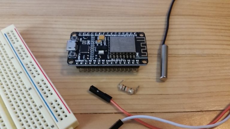
The Parts
Makerfocus 2pcs ESP8266 Module ESP-12E NodeMcu LUA WiFi Internet New Version Development Board (cp2102) – Makerfocus 2pcs ESP8266 Module ESP-12E NodeMcu LUA WiFi Internet New Version Development Board
Ocr TM 5 Pcs NTC 10K 3950 Ohm Waterproof Digital Thermal Temperature Sensor Probe 1M – Ocr TM 5 Pcs NTC 10K 3950 Ohm Waterproof Digital Thermal Temperature Sensor Probe 1M
A 10k Ohm resistor – 10K Ohm, 1/4 Watt, 5%, Carbon Film Resistors (pack of 100)
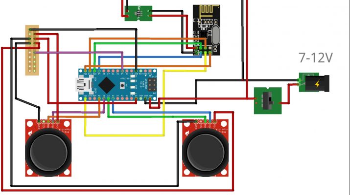
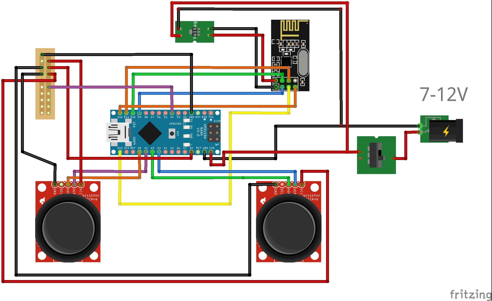
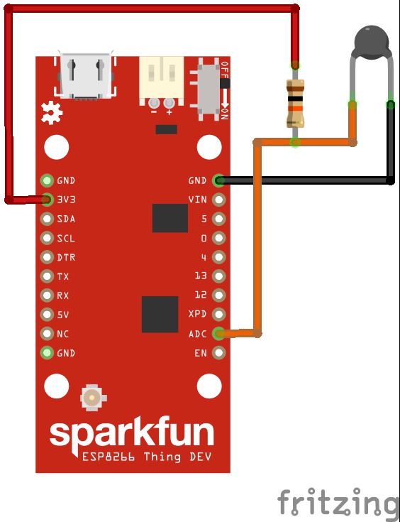
The Schematic:
esp8266 temperature probe

The Code:
byte NTCPin = A0;
#define SERIESRESISTOR 10000
#define NOMINAL_RESISTANCE 10000
#define NOMINAL_TEMPERATURE 25
#define BCOEFFICIENT 3950

void setup(){
Serial.begin(9600);
}
void loop(){
float ADCvalue;
float Resistance;
ADCvalue = analogRead(NTCPin);
Serial.print("Analoge ");
Serial.print(ADCvalue);
Serial.print(" = ");
Resistance = (1023 / ADCvalue) - 1;
Resistance = SERIESRESISTOR / Resistance;
Serial.print(Resistance);
Serial.println(" Ohm");

float steinhart;
float farthat;
steinhart = Resistance / NOMINAL_RESISTANCE; // (R/Ro)
steinhart = log(steinhart); // ln(R/Ro)
steinhart /= BCOEFFICIENT; // 1/B * ln(R/Ro)
steinhart += 1.0 / (NOMINAL_TEMPERATURE + 273.15); // + (1/To)
steinhart = 1.0 / steinhart; // Invert
steinhart -= 273.15; // convert to C
farthat = (steinhart*1.8) + 32;

Serial.print("Temperature ");
Serial.print(steinhart);
Serial.println(" oC");
Serial.print("Temperature ");
Serial.print(farthat);
Serial.println(" F");
delay(1000);
}

Tags: , , | Comments

DIY Drone/Quad Part 2 – Transmitter

| January 26, 2018
Photo Credit: Keith Knoxsville
A Hen and a Drake Green Teal on the truck bed. Not a limit on anything, but a fun morning out.

In this part of the DIY drone/quad build, we are working on a transmitter. It would have been nice to have an R/C transmitter and receiver on hand, but I didn’t so I put one together from parts on the build sheet from Part 1 of these posts.

I mounted everything to a sheet of plexiglass, but you could use any easy to shape material. I plan to place all my components inside a 3d printed case, but that’s another post.

The parts we’ll use are (1)Arduino Nano, (1)nrf24 module, (1)Battery Holder Or Battery Pack, (2)joysticks, (1)3.3v regulator, and a handful of jumper wires, or you can solder everything together. I also held some things in place with zip ties while prototyping. Adding a switch is optional if you use jumper wires. My prototype on/off switch was a matter of plugging in the power wire to the Arduino VIN pin.

Here is the wiring diagram for the transmitter. We’ll upload and test code via the Arduino IDE later.

What are we doing?

  • We are simply using an Arduino to interpret x and y axis inputs from each joystick. These will be our Throttle, Yaw, Pitch, and Roll.
  • We are sending that signal via the nrf24 radio.
  • The 3.3v regulator is required to supply steady 3.3 volts, and steady amps to the radio, which the Arduino 3v out pin cannot do on its own.
  • A switch is used for on and off power.
  • You might also notice I am adding a power wire to the pin D4. This is optional, I used it as a hardwired way to ensure the Auxiliary 1 channel signal was always set to high. This can have a switch, and probably should have a resistor added, or could be done arbitrarily in the code later. What it does in the end is turn on the stability, AKA ‘angle mode’ on the drone, making it much more flyable off the bat.

Need to step forward or backwards? Use the links for the build series below:

  • Program the transmitter, receiver, and flight controller with an Arduino IDE <- Software Using code called Multiwiiv – Part 6
  • Calibrate the Motors with Multiwii code – Part 7
  • Adjust settings and calibrate our gyro via Multiwii GUI AKA a graphical interface/software for your computer – Part 7
Tags: , , , , | Comments

Turning a New Fig Leaf

| January 25, 2018
Photo Credit: Keith Knoxsville
A Hen and a Drake Green Teal on the truck bed. Not a limit on anything, but a fun morning out.

It’s been a difficult couple years for the Gardenisto garden and web publishing effort. I started all my experiments, propagation and production in a zone 9b in California, and then had to co-locate my experimenting and propagating interests between California and Wyoming for nearly 3 years. I then had to co-locate those efforts between California and Idaho for the last 9 months.

That co-location had me spending the majority of the year away from the California garden. But that’s going to change soon. I’ll be back in California for at least 75% of the time, and I’m excited to get the garden in full swing. I’ll literally be turning a new leaf, and I’m even more excited about that, than I am the figs leafing back out.

Hope 2018 has as many exciting life changes and prospects for everyone, and their connections with the horticulural science that surrounds them.

Tags: , , , , | Comments

DIY Drone/Quad Part 1 Intro

| January 10, 2018
Photo Credit: Keith Knoxsville
A Hen and a Drake Green Teal on the truck bed. Not a limit on anything, but a fun morning out.

In this short series of posts, I will show you how to build your own drone, with a transmitter, complete with joysticks, a receiver to receive your instructions, and a flight controller to control the stability and flying characteristics of your quad/drone. The complete build is under 200 bucks, plus or minus a few miscellaneous items.

I also want to make clear, that to use this build guide, a basic knowledge of soldering, electronics, fabrication, and programming, will be necessary. This is not for everyone, but its not beyond learning how to do these things either. While I don’t want to make the build sound complicated, I don’t want to over simplify it either. Expect and or be willing to learn, test, experiment, and be patient; and the experience should be rewarding.

I needed a platform for doing aerial surveys of large agricultural properties for a work contract. Since I have a programming background, experience working with micro-controllers, IOT applications, fabricating, and a history of working with radio control vehicles, it made sense to build a drone from opensource hardware. Building your own drone is actually quite affordable compared to some of the commercial options. With patience, and some tweaking its possible to build a reliable drone.

The drone is a quad copter design that uses arduino microcontrollers for the receiver, the transmitter, and flight controller, an mpu6050 sensor for stabilization, nrf24l transceivers for communication, (4)30amp escs, (4)2212/13 1000kv motors, (4) 10×4 props, (2) 3000mah 30C li-po batteries, and a large frame built from whatever you have on hand. Or you can build it from cheap wood materials.

The cost when finished and flying is less than 200 dollars. Compare that to a much more expensive drone, that you’d never really want ‘modify’ or make your own because of the risk you might damage it. Of course, a more expensive version from more expensive parts can be made. But it hurts a tad less when you crash less expensive materials.

The programming that controls the quad is open source code, uploaded via the Arduino IDE, and configured via Multiwii Software(software that helps you visualize and set settings on the quad/drone). Its based primarily on the hard work and public contributions of many generous programmers, and developers.

To Summarize, We will:

  • Program the transmitter, receiver, and flight controller with an Arduino IDE <- Software Using code called Multiwiiv – Part 6
  • Calibrate the Motors with Multiwii code – Part 7
  • Adjust settings and calibrate our gyro via Multiwii GUI AKA a graphical interface/software for your computer – Part 7
  • Go Fly

In the interest of full disclosure, I make an affiliate commission if you use the links below. So if you find this build log helpful, and want to support more quality posts, then use the comprehensive list of Amazon links below, Thanks.

Electronics Parts List:

  • (4) 2212/13 1000kv motor + 30 amp ESC – http://amzn.to/2BiJhyE
  • (3) Arduino Nanos (receiver board, flight controller, transmitter board- http://amzn.to/2G5Rg5R
  • NRF24L 2.4g transceiver set (will actually transmit and receive signals) – http://amzn.to/2F03Lyc
  • mpu6050 (gyro accellerometer to keep us stable) – http://amzn.to/2F1RXeS
  • (2) 3000mah 30c Lipo Battery – http://amzn.to/2COdaZj
  • 10×4 props w/aluminum hubs (included in motor esc kit
  • (2) 3.3v voltage regulators (provide the right voltage and stable current to the transmitter and receiver) – http://amzn.to/2F1mSrO
  • Power distribution board with Deans Type Plugs – http://amzn.to/2DvWfz7
  • Joysticks (this is a 10 pack for the price of 2, you only need 2 – http://amzn.to/2G50kbc
  • 120 piece Jumper wire set – http://amzn.to/2DqX8of
  • 6AA Battery Box to power the transmitter. However the ideal power source would be a 7 to 12v MAX battery for the Arduino to provide stable power
  • A mix pack of zip ties ranging from 4 inches up to around 10 – Wally World has some fun colors.

Frame Parts List:

These are parts for a wood framed version, its easy to make, and parts can be acquired at a Homedepot, Lowe’s, and any craft store that sells 3mm birch. I went to Michael’s.

  • (2) 36″ 1/2″ square hardwood dowels
  • (2) 200mm x 100mm x 3mm birch plywood
  • (8) 4cm x 6cm x 3mm birch plywood pieces
  • A large variety of 4-40 or m3 screws and nuts
Tags: , , , , , , | Comments