Real World Arduino Relay Use

| November 29, 2012
Photo Credit: Keith Knoxsville
A Hen and a Drake Green Teal on the truck bed. Not a limit on anything, but a fun morning out.

Microcontrollers, like the Arduino, are great for manipulating lower voltage devices. On their own, they are limited in terms of the amount of voltage and current they can provide to devices. Many first Arduino projects involve motors, and LEDs, that require the use of transistors and additional external power sources.

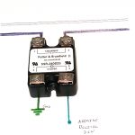
Relay Wire Diagram Control System

Gardenisto DIY Relays

Gardenisto DIY Arduino Relay

To make full use of a microcontroller for home, garden, and hydroponic system manipulation, such as controlling lighting, pumps, and other AC devices, relays(buy one) need to be used.

If we had a legal team, they’d probably want us to cover our ass against stupidity. So here it is:
Warning! This is not a definitive guide to wiring AC applications, working with live electrical currents is dangerous, and can result in serious injuries, death, or damage to one’s property. Gardenisto and its authors are in No Way responsible for any injuries, damages, or deaths, caused by the use or misuse of the information contained on the Gardenisto website. Use of the information is at one’s own risk.

Now that we can carry on, what is a relay?

Very basically, it is an electrically operated switch, where the signal voltage source is completely isolated from the voltage being switched on or off.

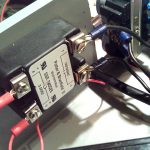
For our example application of manipulating a 150 watt light from a wall outlet, we used a 120 volt 25 amp DC – AC solid state relay that will switch on when a voltage as low as 3 volts is applied. A suitable 10 amp ss relay can be purchased from suppliers like this one – Jameco

This works perfectly with the Arduino 5 volt output, on a digital pin. Not all microcontrollers will operate at 5 volts, some will operate at around 3.3v, so it is critical to understand the hardware you are using, and the interoperability of all your components.

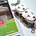
Unplugged, and unpowered, we wired the relay to an appropriate gauge Black AC wire, and finished the AC wiring to an AC wall receptacle mounted to our project enclosure. The receptacle was also selected based on application, and is rated to handle the amperage of our lighting.

While the diagram for wiring a relay is quite simple, simple wiring mistakes can have serious consequences. So be careful, double check yourself, and never work with live electrical currents.

The remaining portion of the system requires the output of the microcontroller. A script turns the digital state of a pin HIGH. The high state toggles the relay, allowing current to flow through the relay.

The other end of the relays DC side is grounded, per the diagram.

Tags: , , , , | Comments

Grow Garlic from Bulbils (seed)

| November 27, 2012
Photo Credit: Keith Knoxsville
A Hen and a Drake Green Teal on the truck bed. Not a limit on anything, but a fun morning out.

Garlic Bulbils (seeds)Most people grow garlic from cloves. The bulbs are broken apart, and individual cloves pulled off. Cloves exhibit obvious signs that they are ready to plant. Roots grow from the bottom basal plate, and the tops turn greenish.

If garlic is allowed to grow out, it will produce a long central stalk with a flower and bulb. The bulb will contain tiny bulbils that are suitable for planting.

Unlike the cloves pulled from a mature bulb of garlic, bulbils will take more than one season to grow. Some varieties will take longer than others.

The benefit however, is that 10 garlic bulbs might produce 5 to 10 cloves, whereas the same plant can produce as many as 100 bulbils or more. The amount of bulbils will depend on the variety.

At the end of last season we collected 15 bulbs and collected nearly 300 bulbils. In fall, we replanted two cloves, and about 100 bulbils, about three bulbils per ½” deep hole.

In retrospect, we should have planted more garlic cloves to have more for immediate consumption in spring, but we ate them instead! This planting will yield two bulbs, with around 10 to 30 cloves, and a little over 30 smaller garlic plants. In warmer climates, garlic is ready to be harvested as early as spring.

If you live in a cooler climate and are uncertain of when to harvest, wait until half the garlic plant is dead. Remove the bulbs from the ground, and clean them off with a rinse of cool water.

A lot of people say not to wash after harvest, but we do it to remove extra dirt. Just be careful not to bruise your garlic. To prevent excess moisture, gently pat them dry with a towel. Let the garlic dry in a cool dry place out of the sunlight.

Depending on the temperatures and size of the bulbs, the skin on the bulbs will turn paper like and the cloves will be ready for consumption in as little as a few days or as long as a couple weeks.

UPDATE 6-18-2014
Made garlic bread, and processed some garlic for Kimchi. Guess where the garlic came from! Its beautiful too.
gyo heirloom garlic

Tags: , , | Comments

Analog Soil Moisture Sensor

| November 20, 2012
Photo Credit: Keith Knoxsville
A Hen and a Drake Green Teal on the truck bed. Not a limit on anything, but a fun morning out.

There are a lot of DIY moisture sensor articles out there. They are quite basic in principle. Gardenisto articles assume basic knowledge of programming, microcontrollers, and circuit design. We generally prefer to use the Arduino for our applications, as it is so widely used and supported. Our example code is also written in C, and intended for use on the Arduino.

This article focuses on the principle of analog sensor measuring via the Arduino microcontroller, as well as real world usage in a hydroponic coco coir growing medium.

How does a moisture sensor work? As water saturation increases, so does the conductivity of the soil or growing medium. If a small electric current is applied to one sensor lead, then at some fraction of that current should be measurable on another sensor lead a small distance away.

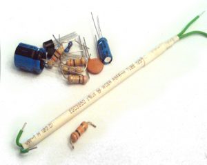
Galvanized nails are also commonly used, simple and effective, but for our basic moisture sensor, we went a little more compact. Two lengths of insulated steel jumper wires are secured in heat shrink tubing. The ends are left exposed. On one end the exposed leads are bent almost 180 degrees back. Caution should was taken to ensure the bent leads are not in contact with one another.

The wires are inserted into a small diameter aluminum tube, just short enough to leave both ends exposed and workable.

DIY Moisture Sensor

Whilst leaving both ends exposed and workable, wrap and secure heat shrink tubing beyond the full length of the tube. The entire thing should feel rigid. This will allow the sensor to hold up to being moved from location to location, and a little abuse.

Our example keeps the wiring fairly simple. It is possible to over complicate the circuit with transistors, or a power source that flips back and forth to prevent an electroplating effect and corrosion of the sensor leads, but for our example we left it simple.

We did add a variable 100k potentiometer to make minor mechanical adjustments.

We ran the power wire to a digital pin, the ground pin to the ground, and the sensor wire to an analog pin on our microcontroller. Our microcontroller is an Arduino, based on the C programming language. They are inexpensive, and have made professional level hardware interfacing available to any hobbyist.

To check soil moisture, we turn on the digital pin which powers the sensor, and give it a fraction of a second to stabilize. We then take analog readings on our analog pin. The readings are done inside of a loop to gather 20 readings before taking the average.


for (i = 0; i < 20; i++){   val = val + analogRead(analogMoisture); } val = val / 20; // take average val = val / 4; // scale to 8 bits (0 - 255)

The digital power pin for the sensor is then turned off. The result is printed to the serial monitor. The following code was extracted from a larger coding block of a more advanced sensor, and formatted to run independently as a simple Arduino program. Entering ‘2’ into the serial monitor will return readings.


/*
* Simple analog moisture sensor.
*
* Leave us a question or comment at http://www.gardenisto.com
*
************************************************************/

int analogMoisture = 0; // pin number of analog moisture sensor readings
int digitalSensorPower = 12; // power up/down pin for sensor readings

int i; // variable used in FOR loops as counter
int val; // variable for reading Moisture status
int intSerialVal = 0;

void setup() {
   pinMode(analogMoisture, INPUT);
   pinMode(digitalSensorPower, OUTPUT);
   Serial.begin(9600);
}

void loop(){

   intSerialVal = Serial.read();
   if ( intSerialVal == '0') {
     digitalWrite(digitalSensorPower, HIGH);
     delay(10); // 10 milisecond delay for stability post power on

     for (i = 0; i < 20; i++){        val = val + analogRead(analogMoisture); // sensor on analog pin 0      }      val = val / 20; // average      val = val / 4; // scale to 8 bits (0 - 255)      Serial.println(val); // Send Sensor Readings      digitalWrite(digitalSensorPower, LOW);      } }

So what does the returning value mean? Before using our sensor on our coco coir growing medium, we created a set of controls by measuring cold water, warm water, and air. The values we attained were: H20 cold:149-146, H20 warm:163-161, Air:0. For a healthy plant in our growing environment, we try and let soil cycle between partially dry, and wet but not over watered. We determined our plant health was optimal when the coco coir moisture level was in the 120-127 range after watering.

Of course, there are additional considerations to make, as you'll notice from the controls. The electro conductiviy of water changes with temperature as well as the level of salinity caused by nutrients in the growing medium. I'll expand on these issues in a more advanced post, but for simple moisture monitoring this method is simple and effective.

Tags: , , , | Comments